初级会员

- 积分
- 60
- 金钱
- 60
- 注册时间
- 2021-6-16
- 在线时间
- 21 小时
|
1金钱
本帖最后由 dmingshen 于 2021-6-16 17:10 编辑
芯片为STM32F407ZGT6
Tim_pwm.c
#include "Tim_pwm.h"
#include "Gpio.h"
void TIM2_PWM_Init(u32 arr,u32 psc)
{
GPIO_InitTypeDef GPIO_InitStructure;
TIM_TimeBaseInitTypeDef TIM_TimeBaseStructure;
TIM_OCInitTypeDef TIM_OCInitStructure;
RCC_APB1PeriphClockCmd(RCC_APB1Periph_TIM2,ENABLE);
RCC_AHB1PeriphClockCmd(RCC_AHB1Periph_GPIOA, ENABLE);
GPIO_PinAFConfig(GPIOA,GPIO_PinSource1,GPIO_AF_TIM2);
GPIO_InitStructure.GPIO_Pin = GPIO_Pin_1;
GPIO_InitStructure.GPIO_Mode = GPIO_Mode_AF;
GPIO_InitStructure.GPIO_Speed = GPIO_Speed_100MHz;
GPIO_InitStructure.GPIO_OType = GPIO_OType_PP;
GPIO_InitStructure.GPIO_PuPd = GPIO_PuPd_UP;
GPIO_Init(GPIOA,&GPIO_InitStructure);
TIM_TimeBaseStructure.TIM_Prescaler=psc;
TIM_TimeBaseStructure.TIM_CounterMode=TIM_CounterMode_Up;
TIM_TimeBaseStructure.TIM_Period=arr;
TIM_TimeBaseStructure.TIM_ClockDivision=TIM_CKD_DIV1;
TIM_TimeBaseInit(TIM2,&TIM_TimeBaseStructure);
TIM_OCInitStructure.TIM_OCMode = TIM_OCMode_PWM1;
TIM_OCInitStructure.TIM_OutputState = TIM_OutputState_Enable;
TIM_OCInitStructure.TIM_OCPolarity = TIM_OCPolarity_Low;
TIM_OC2Init(TIM2, &TIM_OCInitStructure);
TIM_OC2PreloadConfig(TIM2, TIM_OCPreload_Enable);
TIM_ARRPreloadConfig(TIM2,ENABLE);
TIM_Cmd(TIM2, ENABLE);
}
void TIM14_PWM_Init(u32 arr,u32 psc)
{
GPIO_InitTypeDef GPIO_InitStructure;
TIM_TimeBaseInitTypeDef TIM_TimeBaseStructure;
TIM_OCInitTypeDef TIM_OCInitStructure;
RCC_APB1PeriphClockCmd(RCC_APB1Periph_TIM14,ENABLE);
RCC_AHB1PeriphClockCmd(RCC_AHB1Periph_GPIOF, ENABLE);
GPIO_PinAFConfig(GPIOF,GPIO_PinSource9,GPIO_AF_TIM14);
GPIO_InitStructure.GPIO_Pin = GPIO_Pin_9;
GPIO_InitStructure.GPIO_Mode = GPIO_Mode_AF;
GPIO_InitStructure.GPIO_Speed = GPIO_Speed_100MHz;
GPIO_InitStructure.GPIO_OType = GPIO_OType_PP;
GPIO_InitStructure.GPIO_PuPd = GPIO_PuPd_UP;
GPIO_Init(GPIOF,&GPIO_InitStructure);
TIM_TimeBaseStructure.TIM_Prescaler=psc;
TIM_TimeBaseStructure.TIM_CounterMode=TIM_CounterMode_Up;
TIM_TimeBaseStructure.TIM_Period=arr;
TIM_TimeBaseStructure.TIM_ClockDivision=TIM_CKD_DIV1;
TIM_TimeBaseInit(TIM14,&TIM_TimeBaseStructure);
TIM_OCInitStructure.TIM_OCMode = TIM_OCMode_PWM1;
TIM_OCInitStructure.TIM_OutputState = TIM_OutputState_Enable;
TIM_OCInitStructure.TIM_OCPolarity = TIM_OCPolarity_Low;
TIM_OC1Init(TIM14, &TIM_OCInitStructure);
TIM_OC1PreloadConfig(TIM14, TIM_OCPreload_Enable);
TIM_ARRPreloadConfig(TIM14,ENABLE);
TIM_Cmd(TIM14, ENABLE);
}
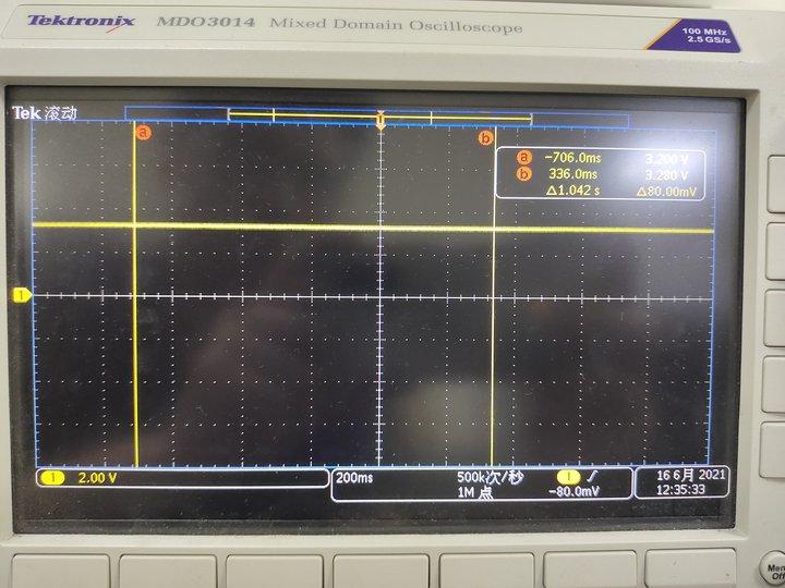
主函数通过TIM_SetCompare1(TIM2,led0pwmval)修改占空比,但是PA1输出的电压一直为+3.3V,不是脉冲:
在线急等,谢谢高手
|
最佳答案
查看完整内容[请看2#楼]
https://blog.csdn.net/mcuwangzai/article/details/79319258
已解决
|


 /1
/1 


 |手机版|OpenEdv-开源电子网
( 粤ICP备12000418号-1 )
|手机版|OpenEdv-开源电子网
( 粤ICP备12000418号-1 )


 发表于 2021-6-16 17:07:16
 楼主
楼主


 发表于 2021-6-17 23:43:38
