README
USMART example
1 Brief
The function of this code is to call the function in the program through USMART to realize the state control of the LED.
2 Hardware Hookup
The hardware resources used in this experiment are:
- LED - PA8
- USART1 - PA9\PA10
- TIM2
The USMART components used in this experiment are application software, so there is no corresponding connection schematic.
3 STM32CubeIDE Configuration
Let's copy the project from 04_UART and name both the project and the.ioc file 11_USMART. Next we start the configuration by double-clicking the 11_USMART.ioc file.
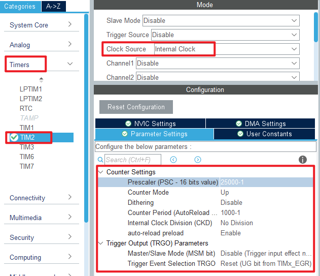
TIM2 is used in this experiment. Click Timers > TIM2 and set it as shown below:
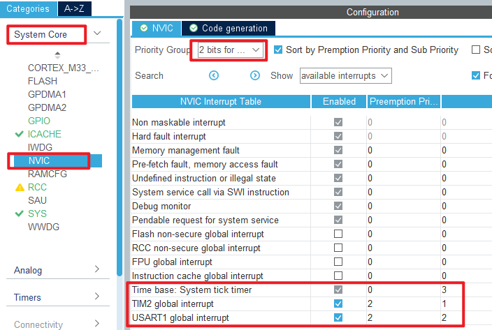
The TIM2 used in this experiment will overflow every 1 ms to generate an interrupt, so the configuration of the NVIC is shown as follows:
Click File > Save, and you will be asked to generate code.Click Yes.
In this experiment, the USMART folder will be ported, which contains the following files:

code
usmart_port.c
Porting USMART components is as simple as implementing the four functions in this file, which are explained below:
/**
 * @brief      Get the input data stream (string)
 * @note       USMART parses the string returned by the function for information such as the function name and arguments
 * @param      none
 * @retval
 * @arg        0, no data received
 * @arg        Other, stream start address (cannot be 0)
 */
char *usmart_get_input_string(void)
{
  uint8_t len;
  char *pbuf = 0;

  if (g_usart_rx_sta & 0x8000)      /* Complete serial port reception? */
  {
    len = g_usart_rx_sta & 0x3fff;  /* Get the length of the received data */
    g_usart_rx_buf[len] = '\0';     /* Add the terminator at the end. */
    pbuf = (char*)g_usart_rx_buf;
    g_usart_rx_sta = 0;             /* Enable next reception */
  }

  return pbuf;
}
As you can see from the preceding code, this function gets the input data from the serial port.
void usmart_timx_reset_time(void)
{
  __HAL_TIM_CLEAR_FLAG(&htim2, TIM_FLAG_UPDATE); /* Clear the interrupt flag bit */
  __HAL_TIM_SET_AUTORELOAD(&htim2, 0XFFFF);      /* Set the reload value to the maximum */
  __HAL_TIM_SET_COUNTER(&htim2, 0);              /* Clear counter */
  usmart_dev.runtime = 0;
}
This function resets the runtime functionality and the associated TMR used for the runtime functionality.
uint32_t usmart_timx_get_time(void)
{
  if (__HAL_TIM_GET_FLAG(&htim2, TIM_FLAG_UPDATE) == SET)  /* During the run, a timer overflow occurs */
  {
    usmart_dev.runtime += 0XFFFF;
  }
  usmart_dev.runtime += __HAL_TIM_GET_COUNTER(&htim2);
  return usmart_dev.runtime;                               /* Return count value */
}
The function is capable of handling a single timer overflow, so the maximum amount of time that can be obtained is twice the maximum timer count.
void TIM2_IRQHandler(void)
{
  /* overflow trap */
  if(__HAL_TIM_GET_IT_SOURCE(&htim2,TIM_IT_UPDATE)==SET)
  {
    usmart_dev.scan();                        /* usmart scan */
    __HAL_TIM_SET_COUNTER(&htim2, 0);;        /* Clear counter */
    __HAL_TIM_SET_AUTORELOAD(&htim2, 100);    /* Restore the original Settings */
  }
  __HAL_TIM_CLEAR_IT(&htim2,  TIM_IT_UPDATE);				/* Clear the interrupt flag bit */
}
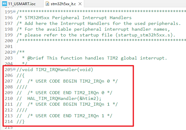
Note that since the interrupt service function is also defined in stm32h5xx_it.c, the definition in stm32h5xx_it.c should be masked, as shown in the following figure:
Now that the porting of the USMART component is almost complete, you can add the debug functions to the usmart_nametab array in the usmart_config.c file .
main.c
In the while loop of main, only the delayed function is called, as follows:
int main(void)
{
  /* USER CODE BEGIN 1 */

  /* USER CODE END 1 */

  /* MCU Configuration--------------------------------------------------------*/

  /* Reset of all peripherals, Initializes the Flash interface and the Systick. */
  HAL_Init();

  /* USER CODE BEGIN Init */

  /* USER CODE END Init */

  /* Configure the system clock */
  SystemClock_Config();

  /* USER CODE BEGIN SysInit */

  /* USER CODE END SysInit */

  /* Initialize all configured peripherals */
  MX_GPIO_Init();
  MX_ICACHE_Init();
  MX_USART1_UART_Init();
  MX_TIM2_Init();
  /* USER CODE BEGIN 2 */
  stm32h503cb_show_mesg();
  /* USER CODE END 2 */

  /* Infinite loop */
  /* USER CODE BEGIN WHILE */
  while (1)
  {
    HAL_Delay(500);   		 /* delay 500ms */
    /* USER CODE END WHILE */

    /* USER CODE BEGIN 3 */
  }
  /* USER CODE END 3 */
}
There are two separate lines of code to add, as shown here:
/* LED state setting function */
void led_set(uint8_t sta)
{
    LED(sta);
}

/* Function arguments call the test function */
void test_fun(void(*ledset)(uint8_t), uint8_t sta)
{
    ledset(sta);
}
The led_set function is used to set the state of the LED. The second function, test_fun, tests USMART's support for function arguments.
4 Running
4.1 Compile & Download
After the compilation is complete, connect the DAP and the Mini Board, and then connect to the computer together to download the program to the Mini Board.
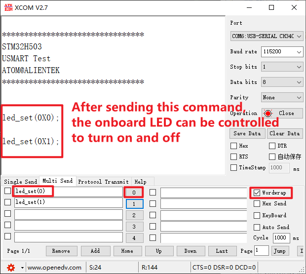
4.2 Phenomenon
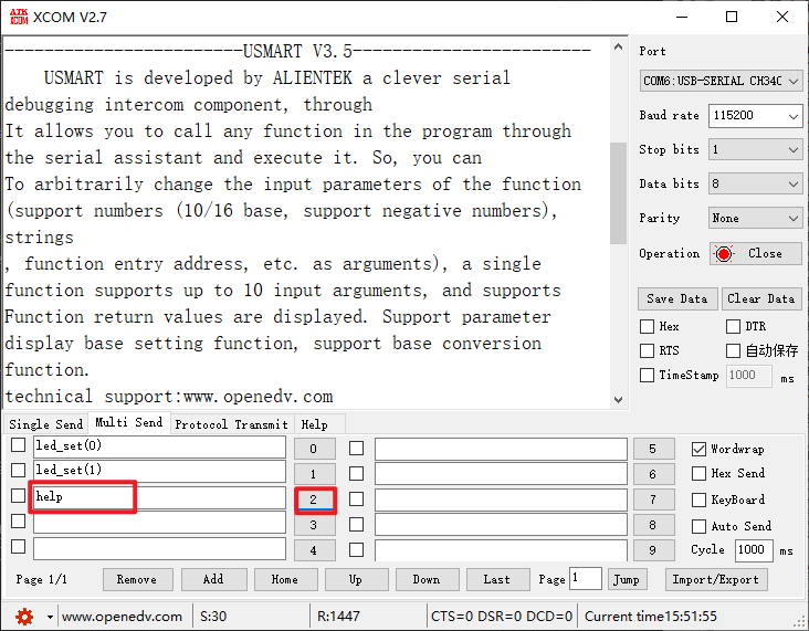
Press the reset button to restart the Mini Board, observe the LED flashing on the Mini Board, open the serial port and the host computer ATK-XCOM can see the prompt information of the experiment, indicating that the code download is successful. We send instructions to complete the response function, as shown in the following figure:
You can also send help to get help, as shown in the following screenshot.