README
RTC example
1 Brief
The function of this code is to generate an RTC wake-up interrupt every second.
2 Hardware Hookup
The hardware resources used in this experiment are:
- LED - PA8
- USART1 - PA9\PA10
- RTC
- ALIENTEK 1.3-inch TFTLCD module(MCU screen only, SPI interface driver)
The RTC used in this experiment is the on-chip resource of STM32H503, so there is no corresponding connection schematic.
3 STM32CubeIDE Configuration
Let's copy the project from 10_TFTLCD_MCU and name both the project and the.ioc file 12_RTC. Next we start the RTC configuration by double-clicking the 12_RTC.ioc file.
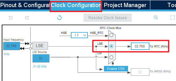
First click Clock Configuration and set it as shown below.
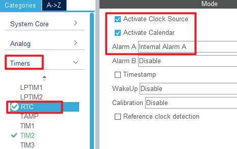
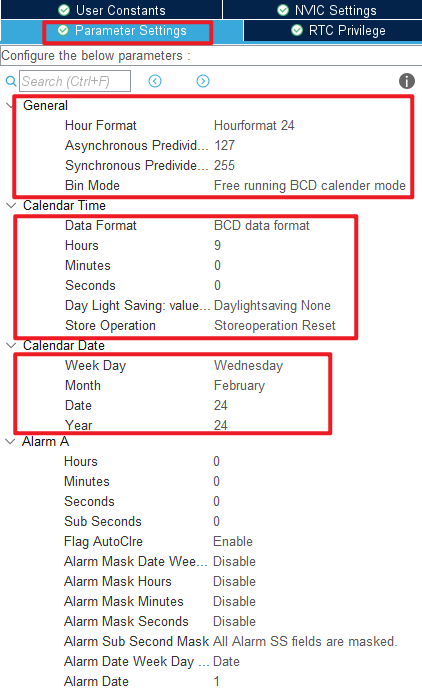
Open Timers > RTC as shown below.
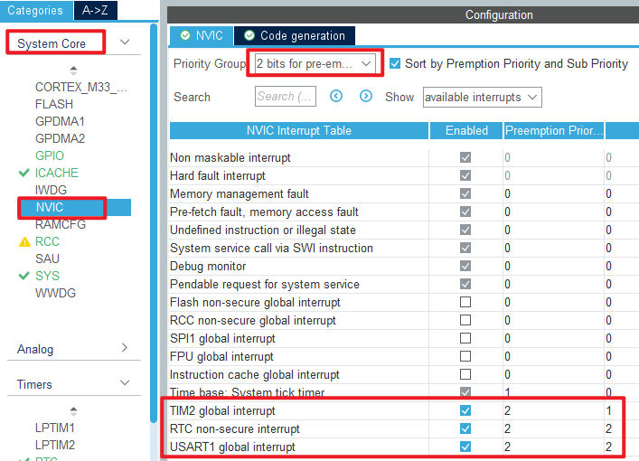
Open NVIC configuration as shown below.
Click File > Save, and you will be asked to generate code.Click Yes.
code
rtc.c
We added a lot of code to rtc.c, so you can open the source code to have a look, but here are the important ones:
HAL_StatusTypeDef rtc_set_time(uint8_t hour, uint8_t min, uint8_t sec, uint8_t ampm)
{
  RTC_TimeTypeDef sTime = {0};

  sTime.Hours = hour;
  sTime.Minutes = min;
  sTime.Seconds = sec;
  sTime.TimeFormat = ampm;
  sTime.DayLightSaving = RTC_DAYLIGHTSAVING_NONE;
  sTime.StoreOperation = RTC_STOREOPERATION_RESET;

  return HAL_RTC_SetTime(&hrtc, &sTime, RTC_FORMAT_BIN);
}
The preceding function is used to set a time.We input a time that will be used as a baseline for subsequent calculations.
void rtc_set_wakeup(uint8_t wksel, uint16_t cnt)
{
  __HAL_RTC_WAKEUPTIMER_CLEAR_FLAG(&hrtc, RTC_FLAG_WUTF);  /* Clear the RTC WAKE UP flag */

  HAL_RTCEx_SetWakeUpTimer_IT(&hrtc, cnt, wksel, 0);       /* Set the reload value and clock */
}

/**
  * @brief  Alarm A secure callback.
  * @param  hrtc RTC handle
  * @retval None
  */
void HAL_RTC_AlarmAEventCallback(RTC_HandleTypeDef *hrtc)
{
  printf("ALARM A!\r\n");
}

/**
  * @brief  Wake Up Timer callback.
  * @param  hrtc RTC handle
  * @retval None
  */
void HAL_RTCEx_WakeUpTimerEventCallback(RTC_HandleTypeDef *hrtc)
{
  printf("WakeUp!\r\n");
}
The latter two functions call the HAL library interrupt public handler function for handling the alarm interrupt.
The function HAL_RTC_AlarmAEventCallback calls the printf function to print a string ALARM A!.
The function HAL_RTCEx_WakeUpTimerEventCallback is used to handle wakeup interrupts. When an interrupt occurs, with this function, print the string WakeUp!.
main.c
In the while loop of the main function, we will read the RTC time and date every 100 milliseconds, as follows:
int main(void)
{
/* USER CODE BEGIN 1 */
uint8_t hour, min, sec, ampm;
uint8_t year, month, date, week;
uint8_t tbuf[40];
uint8_t t = 0;
/* USER CODE END 1 */
/* MCU Configuration--------------------------------------------------------*/
/* Reset of all peripherals, Initializes the Flash interface and the Systick. */
HAL_Init();
/* USER CODE BEGIN Init */
/* USER CODE END Init */
/* Configure the system clock */
SystemClock_Config();
/* USER CODE BEGIN SysInit */
/* USER CODE END SysInit */
/* Initialize all configured peripherals */
MX_GPIO_Init();
MX_ICACHE_Init();
MX_SPI1_Init();
MX_USART1_UART_Init();
MX_RTC_Init();
MX_TIM2_Init();
/* USER CODE BEGIN 2 */
stm32h503cb_show_mesg();
lcd_init(); /* Initialize LCD */
lcd_show_string(30, 50, 200, 16, 16, "STM32", RED);
lcd_show_string(30, 70, 200, 16, 16, "RTC TEST", RED);
lcd_show_string(30, 90, 200, 16, 16, "ATOM@ALIENTEK", RED);
/* USER CODE END 2 */
/* Infinite loop */
/* USER CODE BEGIN WHILE */
while (1)
{
t++;
if ((t % 10) == 0) /* The display data is updated every 100ms */
{
rtc_get_time(&hour, &min, &sec, &m);
sprintf((char *)tbuf, "Time:%02d:%02d:%02d", hour, min, sec);
printf("%s\r\n",tbuf);
lcd_show_string(30, 130, 210, 16, 16, (char *)tbuf, RED);
rtc_get_date(&year, &month, &date, &week);
sprintf((char *)tbuf, "Date:20%02d-%02d-%02d", year, month, date);
printf("%s\r\n",tbuf);
lcd_show_string(30, 150, 210, 16, 16, (char *)tbuf, RED);
sprintf((char *)tbuf, "Week:%d", week);
printf("%s\r\n",tbuf);
lcd_show_string(30, 170, 210, 16, 16, (char *)tbuf, RED);
}
HAL_Delay(100);
/* USER CODE END WHILE */
/* USER CODE BEGIN 3 */
}
/* USER CODE END 3 */
}
The driving LED blinks in the while loop to indicate that the experiment is in progress.
usmart_port.c
In order to facilitate the call verification of RTC-related functions, usmart_nametab is modified in this file as follows:
struct _m_usmart_nametab usmart_nametab[] =
{
#if USMART_USE_WRFUNS == 1      /* If read and write operations are enabled */
  {(void *)read_addr, "uint32_t read_addr(uint32_t addr)"},
  {(void *)write_addr, "void write_addr(uint32_t addr,uint32_t val)"},
#endif
  {(void *)rtc_read_bkr, "uint32_t rtc_read_bkr(uint32_t bkrx)"},
  {(void *)rtc_write_bkr, "void rtc_write_bkr(uint32_t bkrx, uint32_t data)"},
  {(void *)rtc_set_time, "uint8_t rtc_set_time(uint8_t hour, uint8_t min, uint8_t sec, uint8_t ampm)"},
  {(void *)rtc_set_date, "uint8_t rtc_set_date(uint8_t year, uint8_t month, uint8_t date, uint8_t week)"},

  {(void *)rtc_get_week, "uint8_t rtc_get_week(uint16_t year, uint8_t month, uint8_t day)"},
  {(void *)rtc_set_alarm, "void rtc_set_alarm(uint8_t week, uint8_t hour, uint8_t min, uint8_t sec)"},
};
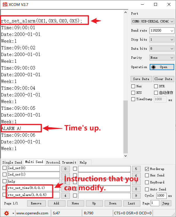
The related functions of RTC are added to USMART, so that RTC time and alarm clock can be set directly through the serial port.
4 Running
4.1 Compile & Download
After the compilation is complete, connect the DAP and the Mini Board, and then connect to the computer together to download the program to the Mini Board.
4.2 Phenomenon
Press the reset button to restart the Mini Board, observe the LED flashing on the Mini Board, open the serial port and the host computer ATK-XCOM can see the prompt information of the experiment, indicating that the code download is successful. We use the serial port to debug the RTC phenomenon as shown below: