README
Blink example
1 Brief
The main function of this code is to let the onboard LED blink alternately at a frequency of 500 milliseconds.
2 Hardware Hookup
The hardware resources used in this experiment are:
- LED - PA8
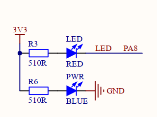

Opening the schematic we can see that the LED pin is connected to the PA8 pin of the MCU. The positive terminal of the LED is connected to the voltage positive terminal through the current limiting resistor, while the negative terminal is connected to the PA8 pin of the MCU. Therefore, by controlling the PA8 pin output low level, the LED can be lit; Output high level, will extinguish the LED.
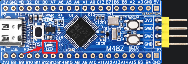
The position of the LED in the Mini Board is shown as follows:
3 STM32CubeIDE Configuration
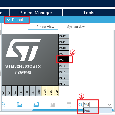
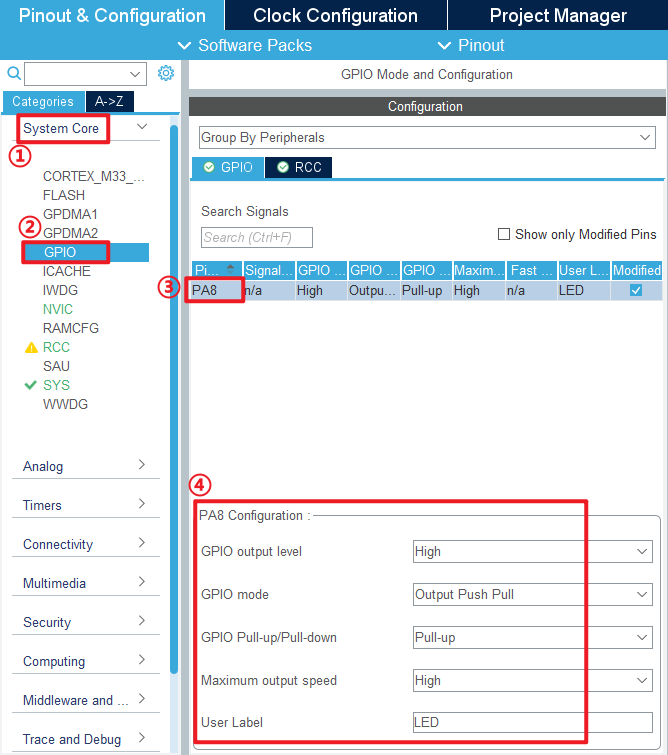
In this tutorial, I'll show you how to configure the Blink example in STM32CubeIDE. Let's create a STM32CubeIDE project. If you can't do that at this step, check out the STM32CubeIDE_Usage_Guide we provided. First, after entering the configuration interface of STM32CubeIDE, enter PA8 in the pin search to find the pin, and click the PA8 pin.
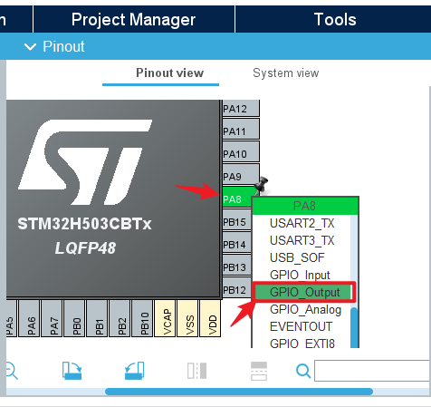
We click on the PA8 pin that blinks and select GPIO_Output from the reuse function that pops up.
Click System Core > GPIO ,and we can further configure IO. The working mode of the I/O port is configured in detail here.
GPIO output level is configured to output high level, and the LED state is off after power-on.
GPIO mode is used to set the IO port Output mode to 'Output Push Pull'.
GPIO Pull-up/Pull-down is used to set whether the IO port is pull-up or pull-down or no pull-up. In this experiment, we set it as pull-up.
Maximum output speed is used to set the output speed of the I/O port. We set it to high speed.
User Label is used to set the initial IO port Pin value as our custom macro.
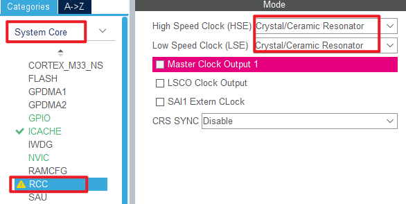
Next configure the clock, first we select the RCC option in the System Core, here we change to the external crystal/ceramic oscillator.
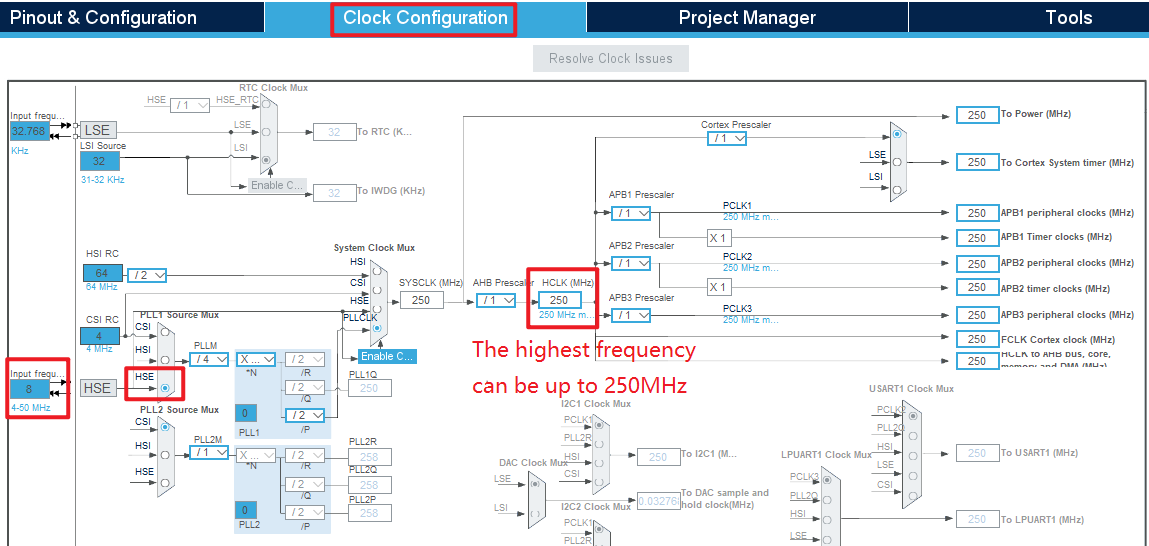
Enter Modify Clock Settings, in the Clock Configuration screen, if the block diagram is blue, it indicates that the clock source is available. If the block diagram is gray, it cannot be used.
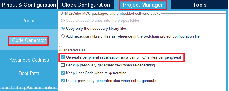
Then go to the configuration project format and check the Generate peripheral initialization as a pair of '.c/.h' files per peripheral option, so that corresponding.c and.h files can be independently generated. In order not to have the code all piled up in the main.c file, it is also easier to view.
Click File > Save, and you will be asked to generate code.Click Yes.If you don't know how to generate code here, you can first read the STM32CubeIDE_Usage_Guide that we provide.
code
Then we added a BSP folder in the file, which stored the led driver file of this experiment, led.c did not write any content, we only added the relevant macro definition in led.h, here look at the code of led.h.
led.h
/* LED port definition */
#define LED(x)   do{ x ? \
                      HAL_GPIO_WritePin(LED_GPIO_Port, LED_Pin, GPIO_PIN_SET) : \
                      HAL_GPIO_WritePin(LED_GPIO_Port, LED_Pin, GPIO_PIN_RESET); \
                  }while(0)      /* turn over LED */

/* LED port defined in reverse */
#define LED_TOGGLE()   do{ HAL_GPIO_TogglePin(LED_GPIO_Port, LED_Pin); }while(0) /* turn over LED */
In the above code, it can be seen that when x is 1, LED(1) is HAL GPIO WritePin(LED GPIO Port, LED Pin, GPIO PIN SET), indicating that the port bit of the LED is set to 1, the port LED Pin outputs a high level, and the LED is off.
When x is 0, LED(0) is HAL GPIO WritePin(LED GPIO Port, LED Pin, GPIO PIN RESET), indicating that the port bit of the LED is set to 0, the port LED Pin output is low, and the LED is on.
In addition, call the HAL_GPIO_TogglePin function to invert the state of the pin.
main.c
Note that most of main.c will be auto-generated by CubeMX, so you only need to worry about the parts between the / USER CODE / guards.
int main(void)
{
  /* USER CODE BEGIN 1 */

  /* USER CODE END 1 */

  /* MCU Configuration--------------------------------------------------------*/

  /* Reset of all peripherals, Initializes the Flash interface and the Systick. */
  HAL_Init();

  /* USER CODE BEGIN Init */

  /* USER CODE END Init */

  /* Configure the system clock */
  SystemClock_Config();

  /* USER CODE BEGIN SysInit */

  /* USER CODE END SysInit */

  /* Initialize all configured peripherals */
  MX_GPIO_Init();
  MX_ICACHE_Init();
  /* USER CODE BEGIN 2 */

  /* USER CODE END 2 */

  /* Infinite loop */
  /* USER CODE BEGIN WHILE */
  while (1)
  {
    LED(0);     /* turn on LED */
    HAL_Delay(500);
    LED(1);     /* turn off LED */
    HAL_Delay(500);
    /* USER CODE END WHILE */

    /* USER CODE BEGIN 3 */
  }
  /* USER CODE END 3 */
}
4 Running
4.1 Compile & Download
After compiling, download the code to the Mini Board with DAP Debugger, if you do not know how to download, see the STM32CubeIDE_User_Guide in the Running related chapters.
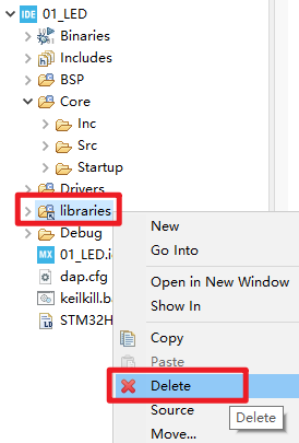
The structure of the source code here is not quite the same as the code structure generated by our STM32CubeIDE_User_Guide, because we have optimized the structure of some files here to achieve the purpose of reducing the file size. If you want to modify the.ioc file based on this source code, just regenerate the code after modifying the.ioc file and delete the libraries folder, as shown in the following figure:
4.2 Phenomenon
Press the reset button to restart the Mini Board and observe the actual result of the LED on the Mini Board. After normal operation, the red LED will blink periodically.