README
Basic timer interrupt example
1 Brief
The function of this code is to flip the state of the LED in the interrupt service function of the basic timer 6.
2 Hardware Hookup
The hardware resources used in this experiment are:
- LED - PA8
- USART1 - PA9\PA10
- TIM6
The TIM6 used in this experiment is the on-chip resource of STM32H503, so there is no corresponding connection schematic diagram.
3 STM32CubeIDE Configuration
Let's copy the project from 04_UART and name both the project and the.ioc file 07_BTIM. Next we start the BTIM configuration by double-clicking the 07_BTIM.ioc file.
First, click Timers > TIM6, and the configuration is as follows:
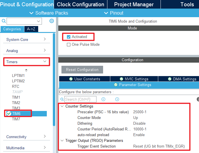
As can be seen from the figure above, we configure the automatic reload value as (10,000-1), the pre-divider value as (25,000-1), and the clock frequency of TIM6 is 250MHz, so the count frequency of TIM6 is 1KHz.
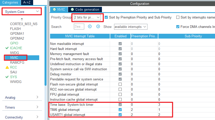
The configuration of the NVIC is shown below:
Click File > Save, and you will be asked to generate code.Click Yes.
code
We add some code to the tim.c file's initialization function MX_TIM6_Init, as follows:
tim.c
  /* USER CODE BEGIN TIM6_Init 2 */
  HAL_TIM_Base_Start_IT(&htim6);    /* Enable timer 6 and its update interrupt */
  /* USER CODE END TIM6_Init 2 */
The above function HAL_TIM_Base_Start_IT is used to enable TIM6 and start the update interrupt.
An interrupt callback function has also been added, as shown below:
void HAL_TIM_PeriodElapsedCallback(TIM_HandleTypeDef *htim)
{
    if (htim->Instance == TIM6)
    {
        LED_TOGGLE(); /* turn over LED */
    }
}
The LED is flipped in the update interrupt callback function HAL_TIM_PeriodElapsedCallback. We will determine whether the update is interrupted by TIM6, and if so, perform an LED flip operation.
main.c
Only the delay function is called in the while loop of the main function, the code is as follows:
int main(void)
{
  /* USER CODE BEGIN 1 */

  /* USER CODE END 1 */

  /* MCU Configuration--------------------------------------------------------*/

  /* Reset of all peripherals, Initializes the Flash interface and the Systick. */
  HAL_Init();

  /* USER CODE BEGIN Init */

  /* USER CODE END Init */

  /* Configure the system clock */
  SystemClock_Config();

  /* USER CODE BEGIN SysInit */

  /* USER CODE END SysInit */

  /* Initialize all configured peripherals */
  MX_GPIO_Init();
  MX_ICACHE_Init();
  MX_USART1_UART_Init();
  MX_TIM6_Init();
  /* USER CODE BEGIN 2 */
  stm32h503cb_show_mesg();
  /* USER CODE END 2 */

  /* Infinite loop */
  /* USER CODE BEGIN WHILE */
  while (1)
  {
    HAL_Delay(500);   /* delay 500ms */
    /* USER CODE END WHILE */

    /* USER CODE BEGIN 3 */
  }
  /* USER CODE END 3 */
}
4 Running
4.1 Compile & Download
After the compilation is complete, connect the DAP and the Mini Board, and then connect to the computer together to download the program to the Mini Board.
4.2 Phenomenon
Press the reset button to restart the Mini Board, open the serial port host computer ATK-XCOM, and you can see the experimental prompt message, indicating that the code has been successfully downloaded. Observe the LED flashing every 500 milliseconds on the Mini Board.