README
DAC_Triangular_Wave example
1 Brief
The function of this code is to press the KEY0 button and the PA4 pin outputs 100 triangle wave 1. Press the WKUP button, and the PA4 pin outputs 100 triangle wave 2.
2 Hardware Hookup
The hardware resources used in this experiment are:
- LED - PA8
- USART1 - PA9\PA10
- DAC1 - Channel1(PA4)
- ALIENTEK DS100 oscilloscope
The DAC used in this experiment is an on-chip resource of STM32H503, so there is no corresponding connection schematic.
3 STM32CubeIDE Configuration
We copy the 04_UART project and name both the project and the.ioc file 17_2_DAC_Triangular_Wave.Next we start the DAC configuration by double-clicking the 17_2_DAC_Triangular_Wave.ioc file.
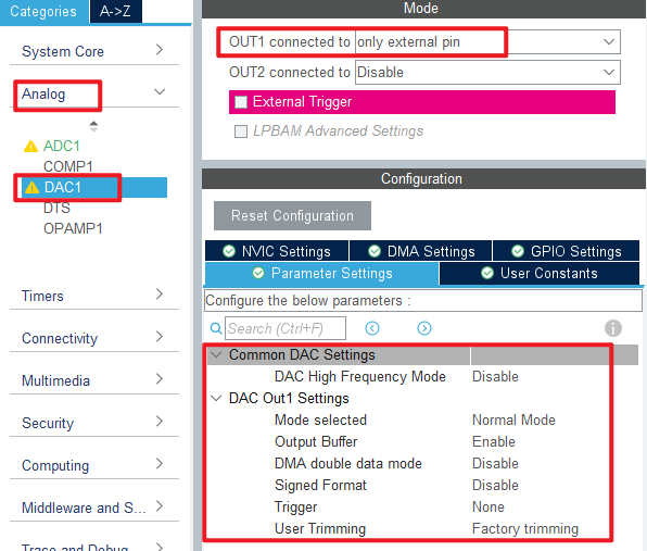
In Pinout&Configuration, click PA4 pin to set mode.

Then open Analog->DAC1 to configure.
Click File > Save, and you will be asked to generate code.Click Yes.
code
We add some code to adc.c, starting with DAC1's initialization function MX_DAC1_Init, as follows.
dac.c
  /* USER CODE BEGIN DAC1_Init 2 */
  HAL_DAC_Start(&hdac1, DAC_CHANNEL_1);  /* Open DAC channel 1 */
  /* USER CODE END DAC1_Init 2 */
This line is added to the initialization function to open DAC channel 1. A separate function has also been added as follows.
void dac_triangular_wave(uint16_t maxval, uint16_t dt, uint16_t samples, uint16_t n)
{
    uint16_t i, j;
    float incval;                           /* incremental change */
    float curval;                           /* current value */

    if ((maxval + 1) <= samples)
    {
        return ;                            /* Data is not valid */
    }

    incval = (maxval + 1) / (samples / 2);  /* Calculate the increment */

    for (j = 0; j < n; j++)
    {
        curval = 0;
        HAL_DAC_SetValue(&hdac1, DAC_CHANNEL_1, DAC_ALIGN_12B_R, curval);     /* I'm going to print 0 first. */
        for (i = 0; i < (samples / 2); i++)                                   /* Output rising edge */
        {
            curval +=  incval;                                                /* New output value */
            HAL_DAC_SetValue(&hdac1, DAC_CHANNEL_1, DAC_ALIGN_12B_R, curval);
            delay_us(dt);                                                     /* delay 5ms */
        }
        for (i = 0; i < (samples / 2); i++)                                   /* Output falling edge */
        {
            curval -=  incval;                                                /* New output value */
            HAL_DAC_SetValue(&hdac1, DAC_CHANNEL_1, DAC_ALIGN_12B_R, curval);
            delay_us(dt);                                                     /* delay 5ms */
        }
    }
}
This function is used to set the DAC channel 1 output to a specified triangular wave.
main.c
Here's the main function.
int main(void)
{
  /* USER CODE BEGIN 1 */
  uint8_t t = 0;
  uint8_t key;
  /* USER CODE END 1 */

  /* MCU Configuration--------------------------------------------------------*/

  /* Reset of all peripherals, Initializes the Flash interface and the Systick. */
  HAL_Init();

  /* USER CODE BEGIN Init */

  /* USER CODE END Init */

  /* Configure the system clock */
  SystemClock_Config();

  /* USER CODE BEGIN SysInit */
  delay_init(250);
  /* USER CODE END SysInit */

  /* Initialize all configured peripherals */
  MX_GPIO_Init();
  MX_DAC1_Init();
  MX_ICACHE_Init();
  MX_USART1_UART_Init();
  MX_ADC1_Init();

  /* USER CODE BEGIN 2 */
  stm32h503cb_show_mesg();
  /* USER CODE END 2 */

  /* Infinite loop */
  /* USER CODE BEGIN WHILE */
  while (1)
  {
    t++;
    key = key_scan(0);                            /* Scan key */

    if (key == KEY0_PRES)                         /* High sampling rate */
    {
        printf("DAC Wave1 \r\n");
        dac_triangular_wave(4095, 5, 2000, 100);  /* Amplitude 4095, sampling point interval 5us,2000 sampling points,100 waveforms */
        printf("DAC None  \r\n");
    }
    else if (key == WKUP_PRES) /* Low sampling rate */
    {
        printf("DAC Wave2 \r\n");
        dac_triangular_wave(4095, 500, 20, 100);  /* Amplitude 4095, sampling point interval 500us,20 sampling points,100 waveforms */
        printf("DAC None  \r\n");
    }

    if (t == 10)
    {
        LED_TOGGLE();
        t = 0;
    }

    HAL_Delay(10);   /* delay 10ms */

    /* USER CODE END WHILE */

    /* USER CODE BEGIN 3 */
  }
  /* USER CODE END 3 */
}
After the initialization of this part of the code, the key is scanned continuously, and according to the scanned key, the DAC channel 1 is controlled to output the triangle wave with the specified amplitude, frequency, and number.
4 Running
4.1 Compile & Download
After the compilation is complete, connect the DAP and the Mini Board, and then connect to the computer together to download the program to the Mini Board.
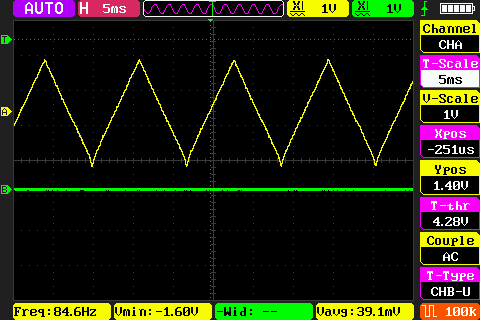
4.2 Phenomenon
Press the reset button to restart the Mini Board, observe the LED flashing on the Mini Board, open the serial port and the host computer ATK-XCOM can see the prompt information of the experiment, indicating that the code download is successful. Connect the PA4 pin with a ALIENTEK DS100 oscilloscope and press the KEY0 and WKUP keys respectively. You can see two different types of triangle waves, as shown in the following figure: