README
ADC_DMA_Multi_Channel example
1 Brief
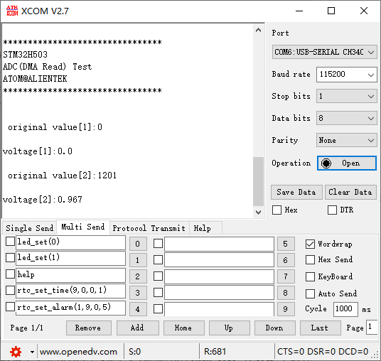
The function of this code is to collect the voltage on channel 1 and channel 7 of ADC through DMA, and display the digital amount of the voltage converted by ADC and the analog amount converted by ADC on the serial port debugging assistant.
2 Hardware Hookup
The hardware resources used in this experiment are:
- LED - PA8
- USART1 - PA9\PA10
- ADC1 - Channel1(PA1)
- ADC1 - Channel7(PA7)
The ADC used in this experiment is an on-chip resource of STM32H503, so there is no corresponding connection schematic.
3 STM32CubeIDE Configuration
We copy the previous chapter project and name both the project and the.ioc file 15_3_ADC_DMA_Multi_Channel.Next we start the ADC configuration by double-clicking the 15_3_ADC_DMA_Multi_Channel.ioc file.
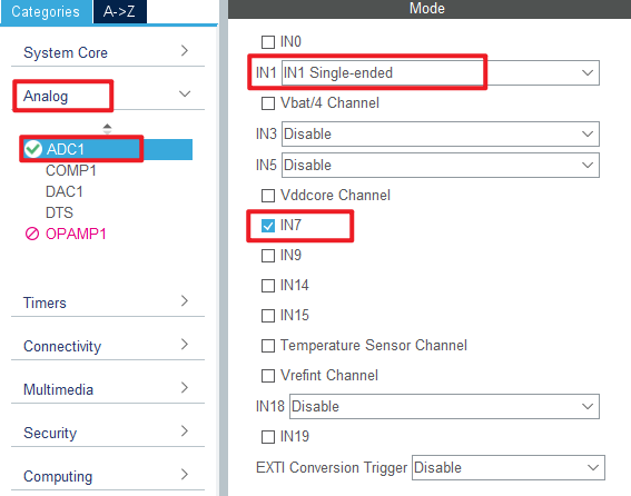
Since this experiment uses one more ADC channel than the experiment in the previous chapter, the ADC channel needs to be reconfigured. Click Analog > ADC1 to set.
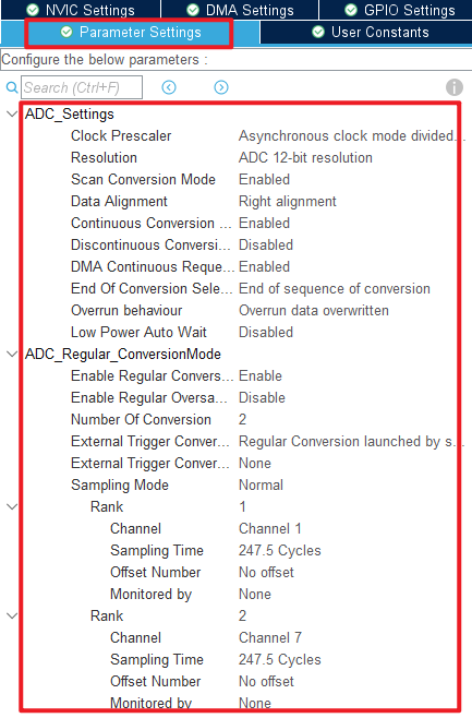
Next are the ADC1 parameters, as shown in the following screenshot.
Click File > Save, and you will be asked to generate code.Click Yes.
The code for the ADC and DMA is the same as in the previous chapter, but we have already covered them and will not repeat them here.
code
main.c
Here's the code in the main function.
/* USER CODE BEGIN PV */
#define ADC_DMA_BUF_SIZE      2 * 50             /* ADC DMA buffer size */
static uint16_t g_adc_dma_buf[ADC_DMA_BUF_SIZE]; /* ADC DMA buffer */

extern uint8_t g_adc_dma_sta; /* DMA transfer completion flag */
/* USER CODE END PV */
int main(void)
{
  /* USER CODE BEGIN 1 */
  uint8_t j;
  uint16_t i;
  uint32_t sum;
  uint16_t adcdata;
  uint16_t voltage;
  /* USER CODE END 1 */

  /* MCU Configuration--------------------------------------------------------*/

  /* Reset of all peripherals, Initializes the Flash interface and the Systick. */
  HAL_Init();

  /* USER CODE BEGIN Init */

  /* USER CODE END Init */

  /* Configure the system clock */
  SystemClock_Config();

  /* USER CODE BEGIN SysInit */

  /* USER CODE END SysInit */

  /* Initialize all configured peripherals */
  MX_GPIO_Init();
  MX_GPDMA1_Init();
  MX_ICACHE_Init();
  MX_ADC1_Init();
  MX_USART1_UART_Init();
  /* USER CODE BEGIN 2 */
  stm32h503cb_show_mesg();
  HAL_ADCEx_Calibration_Start(&hadc1, ADC_SINGLE_ENDED);
  HAL_ADC_Start_DMA(&hadc1, (uint32_t *)g_adc_dma_buf, ADC_DMA_BUF_SIZE);
  /* USER CODE END 2 */

  /* Infinite loop */
  /* USER CODE BEGIN WHILE */
  while (1)
  {
    HAL_ADC_Start(&hadc1);

    if (g_adc_dma_sta == 1)
    {
        for (j = 0; j < 2; j++)
        {
            /* The average value of the ADC data acquired by DMA is calculated */
            sum = 0;

            for (i = 0; i < (ADC_DMA_BUF_SIZE / 2); i++) /* The multiple sampled values of the ADC are mean-filtered */
            {
               sum += g_adc_dma_buf[(2 * i) + j];
            }

            adcdata = sum / (ADC_DMA_BUF_SIZE / 2);     /* averaging */

            /* displaying results */
            printf("\r\n original value[%d]:%d\r\n", j + 1, adcdata);

            voltage = (adcdata * 3300) / 4095;    /* Calculate the actual voltage value (1000 times larger) */
            printf("\r\nvoltage[%d]:%d.%d\r\n", j + 1, voltage / 1000, voltage % 1000);

            g_adc_dma_sta = 0;                    /* Clear the DMA acquisition completion status flag */
        }
    }

    LED_TOGGLE();
    HAL_Delay(1000);   /* delay 500ms */

    /* USER CODE END WHILE */

    /* USER CODE BEGIN 3 */
  }
  /* USER CODE END 3 */
}
The code in this section is very similar to that in the previous chapter.The data for DMA transfers are stored in the g_adc_dma_buf array-two channels are used in this case, so a larger DMA transfer destination memory is required. Each channel uses 50 uint16_t of space for the ADC data. To reduce error, we take the average of the data in the array.
4 Running
4.1 Compile & Download
After the compilation is complete, connect the DAP and the Mini Board, and then connect to the computer together to download the program to the Mini Board.
4.2 Phenomenon
Press the reset button to restart the Mini Board, observe the LED flashing on the Mini Board, open the serial port and the host computer ATK-XCOM can see the prompt information of the experiment, indicating that the code download is successful. When the dupont line is used to connect the PA1 and PA7 pins with different voltage values, the digital and analog voltage of the serial port host computer will also change. It should be noted that the input voltage cannot exceed the 3.3V threshold of the Mini Board, otherwise it may damage the Mini Board. The phenomenon is illustrated in the following figure: