README
LowPower_Standby example
1 Brief
The function of this program is that when KEY0 is pressed, it enters the standby mode, at this time the LCD and LED are off. When WKUP is pressed, the standby mode is exited, the LCD lights up, and the LED blinks normally. Please refer to the contents of 10_TFTLCD_MCU for the specific wiring method of 1.3 inch screen.
2 Hardware Hookup
The hardware resources used in this experiment are:
- LED - PA8
- USART1 - PA9\PA10
- KEY - WKUP(PA0)
- KEY - KEY0(PC13)
- ALIENTEK 1.3-inch TFTLCD module(MCU screen only, SPI interface driver)
This experiment introduces the standby mode in the low power mode and does not involve the connection schematic.
3 STM32CubeIDE Configuration
We copy the 13_3_LowPower_Stop project and name both the project and the.ioc file 13_4_LowPower_Standby.
This experiment is replicated from the previous section, so external interrupt configuration these are already configured. No additional changes to the.ioc file are required. It is only necessary to add the PWR driver file pwr.c/pwr.h. The pwr file for this experiment is different from the one in the previous chapter.
code
pwr.c
The code for this file is as follows.
void pwr_enter_standby(void)
{
  HAL_PWR_ConfigAttributes(PWR_ALL, PWR_PRIV);

  if (__HAL_PWR_GET_FLAG(PWR_FLAG_SBF) != 0)
  {
    /* Clear the standby mode flag */
    __HAL_PWR_CLEAR_FLAG(PWR_FLAG_SBF);
    /* The PWR WAKEUP FLAG1 bit is detected and cleared */
    if (__HAL_PWR_GET_FLAG(PWR_WAKEUP_FLAG1) != 0)
    {
        __HAL_PWR_CLEAR_FLAG(PWR_WAKEUP_FLAG1);
    }
  }

  HAL_PWR_EnableWakeUpPin(PWR_WUCR_WUPEN1);  /* Enable the wake-up function of the KEY UP pin */
  __HAL_PWR_GET_FLAG(PWR_WAKEUP_FLAG1);      /* You need to clear this flag or you will remain awake */
  HAL_PWR_EnterSTANDBYMode();                /* Enter standby mode */
}
The function needs to clear the wake flag before going into standby mode, otherwise it stays awake, and then calls the HAL_PWR_EnterSTANDBYMode function to go into standby mode.
main.c
Here's the main function.
int main(void)
{
/* USER CODE BEGIN 1 */
uint8_t t = 0;
uint8_t key = 0;
/* USER CODE END 1 */
/* MCU Configuration--------------------------------------------------------*/
/* Reset of all peripherals, Initializes the Flash interface and the Systick. */
HAL_Init();
/* USER CODE BEGIN Init */
/* USER CODE END Init */
/* Configure the system clock */
SystemClock_Config();
/* USER CODE BEGIN SysInit */
/* USER CODE END SysInit */
/* Initialize all configured peripherals */
MX_GPIO_Init();
MX_ICACHE_Init();
MX_USART1_UART_Init();
MX_SPI1_Init();
/* USER CODE BEGIN 2 */
stm32h503cb_show_mesg();
lcd_init();
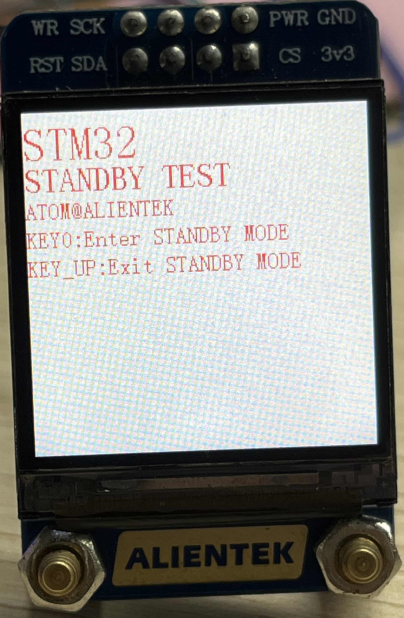
lcd_show_string(0, 5, 200, 32, 32, "STM32", RED);
lcd_show_string(0, 34, 200, 24, 24, "STANDBY TEST", RED);
lcd_show_string(0, 60, 200, 16, 16, "ATOM@ALIENTEK", RED);
lcd_show_string(0, 80, 200, 16, 16, "KEY0:Enter STANDBY MODE", RED);
lcd_show_string(0, 100, 200, 16, 16, "KEY_UP:Exit STANDBY MODE", RED);
/* USER CODE END 2 */
/* Infinite loop */
/* USER CODE BEGIN WHILE */
while (1)
{
key = key_scan(0);
if (key == KEY0_PRES)
{
pwr_enter_standby(); /* Enter standby mode */
}
if ((t % 20) == 0)
{
LED_TOGGLE(); /* Every 200ms, the LED is flipped */
}
HAL_Delay(10);
t++;
/* USER CODE END WHILE */
/* USER CODE BEGIN 3 */
}
/* USER CODE END 3 */
}
The function of this part is to enter the standby mode after pressing KEY0. Then it waits for the external interrupt to wake up. When the WKUP key is pressed, the external interrupt is triggered, and the standby mode is woken up, and then the following program is executed.
4 Running
4.1 Compile & Download
After the compilation is complete, connect the DAP and the Mini Board, and then connect to the computer together to download the program to the Mini Board.
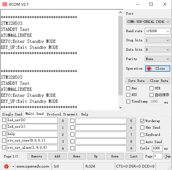
4.2 Phenomenon
Press the reset button to restart the Mini Board, observe the LED flashing on the Mini Board, open the serial port and the host computer ATK-XCOM can see the prompt information of the experiment, indicating that the code download is successful. If the KEY0 button is pressed, the LED and LCD will go off. If the WKUP button is pressed, the LED will resume flashing, the LCD screen will resume display, and the experimental information will be displayed again on the serial port, as shown in the following figure.