README
LowPower_Sleep example
1 Brief
The function of this program is that when the KEY0 is pressed, it enters the Sleep Mode, and the serial port prints Enter Sleep Mode.... When WKUP is pressed to Exit Sleep Mode, the serial port prints Exit Sleep Mode.... You can also see the tips on the 1.3 inch screen, and see the details of the connection method in 10_TFTLCD_MCU.
2 Hardware Description
The hardware resources used in this experiment are:
- LED - PA8
- USART1 - PA9\PA10
- KEY - WKUP(PA0)
- KEY - KEY0(PC13)
- ALIENTEK 1.3-inch TFTLCD module(MCU screen only, SPI interface driver)
This experiment introduces the sleep mode in the low power mode and does not involve the connection schematic.
3 STM32CubeIDE Configuration
Let's copy the project from 13_1_LowPower_PVD and name both the project and the.ioc file 13_2_LowPower_Sleep. Next we start the configuration by double-clicking the 13_2_LowPower_Sleep.ioc file.
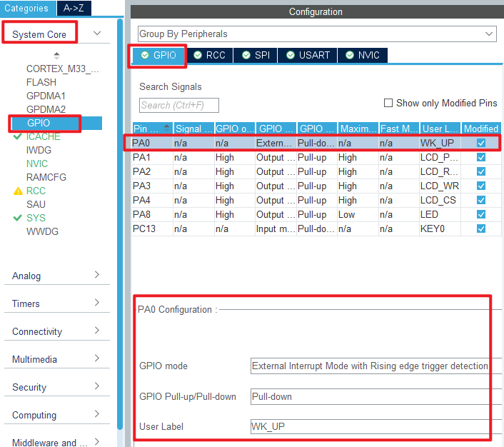
First, click Pinout&Configuration, modify the PA0 pin to the external interrupt wakeup mode as shown below:

The specific parameter configuration of PA0 is shown in the following figure.
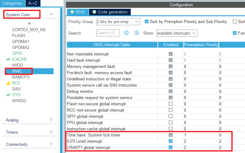
In this experiment, the sleep mode is awakened by external interrupt, so the NVIC should be configured, as shown below:
Click File > Save, and you will be asked to generate code.Click Yes.In addition, we also need to add the PWR driver file pwr.c/pwr.h. The pwr file in this experiment is different from the one in the previous chapter.
code
pwr.c
The code for this file is as follows.
void pwr_enter_sleep(void)
{
  HAL_SuspendTick();  /* Pause the tick clock to prevent wakeup from being interrupted by the tick clock */
  HAL_PWR_EnterSLEEPMode(PWR_MAINREGULATOR_ON, PWR_SLEEPENTRY_WFI); /* Execute the WFI command and enter the sleep mode */
}

/**
 * @brief    External interrupt callback function
 * @param    GPIO Pin : Interrupt pin
 * @note     This function is called by PWR WKUP INT IRQHandler()
 * @retval   None
 */
void HAL_GPIO_EXTI_Callback(uint16_t GPIO_Pin)
{
  if (GPIO_Pin == WK_UP_Pin)
  {
      /* The HAL_GPIO_EXTI_IRQHandler() function has cleared the interrupt flag for us,
       *  so we can call the callback without doing anything */
  }
}
The HAL_PWR_EnterSLEEPMode function is called directly from within the pwr_enter_sleep function to use the WFI command to enter sleep mode.
The latter function is a callback function, we just wake up the sleep mode, we don't have to write another logic program.
main.c
Here's the main function.
int main(void)
{
  /* USER CODE BEGIN 1 */
  uint8_t t = 0;
  uint8_t key = 0;
  /* USER CODE END 1 */

  /* MCU Configuration--------------------------------------------------------*/

  /* Reset of all peripherals, Initializes the Flash interface and the Systick. */
  HAL_Init();

  /* USER CODE BEGIN Init */

  /* USER CODE END Init */

  /* Configure the system clock */
  SystemClock_Config();

  /* USER CODE BEGIN SysInit */

  /* USER CODE END SysInit */

  /* Initialize all configured peripherals */
  MX_GPIO_Init();
  MX_ICACHE_Init();
  MX_USART1_UART_Init();
  MX_SPI1_Init();
  /* USER CODE BEGIN 2 */
  stm32h503cb_show_mesg();
  lcd_init();
  lcd_show_string(0, 5, 200, 32, 32,  "STM32", RED);
  lcd_show_string(0, 34, 200, 24, 24,  "SLEEP TEST", RED);
  lcd_show_string(0, 60, 200, 16, 16,  "ATOM@ALIENTEK", RED);
  lcd_show_string(0, 80, 200, 16, 16, "KEY0:Enter SLEEP MODE", RED);
  lcd_show_string(0, 100, 200, 16, 16, "KEY_UP:Exit SLEEP MODE", RED);
  /* USER CODE END 2 */

  /* Infinite loop */
  /* USER CODE BEGIN WHILE */
  while (1)
  {
    key = key_scan(0);

    if (key == KEY0_PRES)
    {
        lcd_show_string(0, 120, 200, 16, 16, "Enter Sleep Mode...", BLUE);
        printf("Enter Sleep Mode...\r\n");
        pwr_enter_sleep();    /* Enter sleep mode */
        lcd_show_string(0, 120, 200, 16, 16, "Exit  Sleep Mode...", BLUE);
        printf("Exit Sleep Mode...\r\n");
    }

    if ((t % 20) == 0)
    {
        LED_TOGGLE();        /* Every 200ms, the LED is flipped */
    }

    HAL_Delay(10);
    t++;
    /* USER CODE END WHILE */

    /* USER CODE BEGIN 3 */
  }
  /* USER CODE END 3 */
}
The function of this part is to enter the sleep mode when KEY0 is pressed. Then it waits for an external interrupt to wake up. When the WKUP key is pressed, the external interrupt is triggered, the sleep mode is woken up, and the program continues to execute.
4 Running
4.1 Compile & Download
After the compilation is complete, connect the DAP and the Mini Board, and then connect to the computer together to download the program to the Mini Board.
4.2 Phenomenon
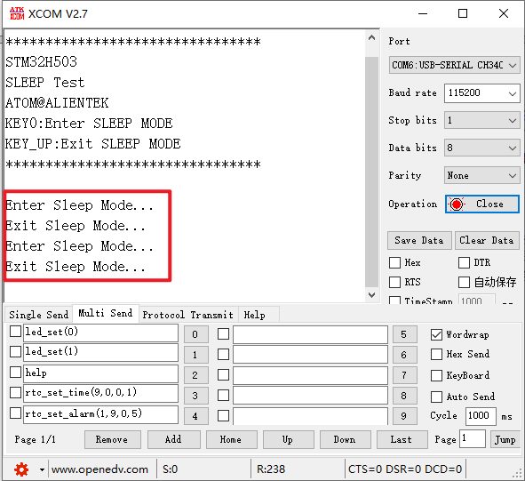
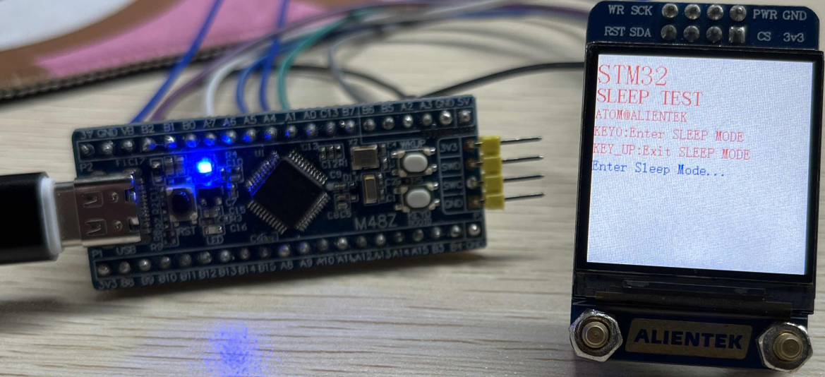
Press the reset button to restart the Mini Board, observe the LED flashing on the Mini Board, open the serial port and the host computer ATK-XCOM can see the prompt information of the experiment, indicating that the code download is successful. If you press the KEY0 button, the serial port will display Enter Sleep Mode.... If you press the WKUP button, the serial port will display Exit Sleep Mode..., there will also be a corresponding prompt message on the LCD screen as shown below.